
Difference between UML 1.0 and UML 2.0
Key Difference: UML stands for Unified Modeling Language. UML 1.0 and UML 2.0 are two different versions of UML. UML 1.0 is greatly influenced by the OMT notations. However, it suffers from weak semantic integration. UML 2.0 tackles the issues related to the weak semantic integration. However, it also suffers from constraints like overloaded notation, lack of precise semantics and lack of methodological basis like usage types, etc.
 UML (Unified Modeling Language) is a design language that is often used to develop and build computer applications. It consists of a family of graphical notations that assists in describing and designing software systems. It is mainly employed in the systems developed using an object-oriented style. UML is independent of implementation language. UML can be used at various stages like analysis, design and programming. There are numerous kinds of UML diagrams like object, package, sequence, state machine, timing, use case, interaction, component structure, communication, component, etc. Jim Rambaugh, Ivar Jacobson and Grady Booch are the original authors of UML. It has been released by the Object Management group in the 1997. UML 1.1 was submitted to the OMG in August 1997 and adopted by the OMG in November 1997.
UML has undergone several phases of evolution. UML 1.0 is based on the Industry standard for object oriented modeling. However, UML 2.0 has been an industry standard focusing on the model-driven application integration. UML 2.0 has various advantages over UML 1.x (all version of UML 1.0) as many new powerful concepts have been added in UML 2.0. UML 2.0 is capable to provide better semantics or definitions. It has also worked to improve the internal structuring.
 UML 1.x is greatly influenced by the OMT notations. However, UML 1.x suffers from weak semantic integration. Later, some other concepts were also merged with UML related to the object oriented methods. The issue of weak semantic integration was handled in the UML 2.0's major revision. UML 1.3, 1.4, and 1.5 also followed as revision versions of UML 1.1.
Later, UML 2.1 came into existences without being released as a formal specification. In 2007, the versions 2.1.1 and 2.1.2 appeared. UML 2.3 was released in May of 2010. It was followed by UML 2.4.1 in August of 2011. UML 2.5 got released in October 2010.
In spite of being better defined than UML 1.5, the state of UML 2.0 is not satisfying enough. It comes with constraints like overloaded notation, lack of precise semantics and also lack the methodological basis like usage types, etc. The development to version 2.0 also extended the set of diagrams, and included 13 types of diagrams:
Class diagram, Object diagram, Component diagram, Composite structure diagram, Use case diagram, Sequence diagram, Communication diagram, State diagram, Activity diagram, Deployment diagram, Package diagram, Timing diagram and Interaction overview diagram. The collaboration diagram from UML 1 is denoted as a communication diagram in the UML 2.0.
Comparison between UML 1.0 and UML 2.0:
|
|
UML 1.0 |
UML 2.0 |
|
Focus |
On a strict build and interpretation to the execution. |
On providing a better version than earlier revisions of UML 1.0 series. |
|
Nodes |
As pseudo states designed for the modeling of flows |
Functions and offers output flows |
|
Parallelism |
Restricted |
Unrestricted |
|
Sequence Diagrams |
(An ordered collection of messages in UML 1.x)
|
(An interaction is defined as an order relation between the actions of sending and receiving messages in UML 2.0) Shift of focus to description of mandatory behavior.
|
|
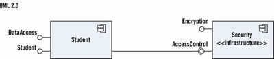
Components and Composite structure Diagram |
Components Interfaces Implementation and use Relations
|
Separation of required and provided interfaces
Port: a class specifying communication endpoints
Connector: an instance of an association between ports representing an ongoing communication
|
|
Model element name |
(UML 1.4) Association end |
(UML 2.0) Member end and Property |
|
Model element name |
Object (when used in activity diagrams) |
Object node |
|
Model element name |
Object (when used in sequence diagrams) |
Lifeline |
|
Model element name |
Activity |
Structured activity node |
|
Model element name |
Decision |
Decision node or merge node |
|
Model element name |
State |
Structured activity node |
Images Courtesy: drdobbs.com
 |
 |
 |
 |
 |
 |
 |
 |
Add new comment