Difference between UML and ERD
Key Difference: UML stands for Unified Modeling Language. ERD stands for Entity Relationship Diagram. UML is a popular and standardized modeling language that is primarily used for object oriented softwares. Entity-Relationship diagrams are used in structured analysis and conceptual modeling. They are often used to graphically represent the logical structure of a database.
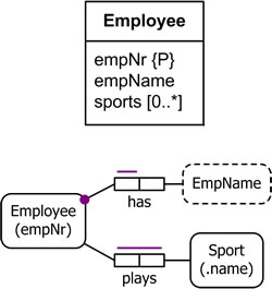
 UML stands for Unified Modeling Language. It has been released by the Object Management group in the 1997. It is a design language that is often used to develop and build computer applications. It consists of a family of graphical notations that assists in describing and designing software systems. It is mainly employed in the systems developed using an object-oriented style. The UML is independent of an implementation language. UML can be used at various stages like analysis, design and programming. There are numerous kinds of UML diagrams like object, package, sequence, state machine, timing, use case, interaction, component structure, communication, component, etc. Jim Rambaugh, Ivar Jacobson and Grady Booch are the original authors of UML.
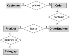
 ERD stands for Entity Relationship Diagram. It works as an important component of a conceptual data model. ERD is often used to graphically represent the logical structure of a database. The model is based on three prime components:
- Entities: It can be any person, object, event or concept about which the data needs to be stored or maintained.
- Attributes: Characteristics of the entities are referred to as attributes.
- Relationships: It describes the association between the entities.
The relationships are further divided into optional and mandatory relationships. Another important term that is associated with the Entity Relationship Diagrams is the cardinality. In a relationship, it identifies the number of instances of an entity that can (or in some cases, must) be associated with another entity. Thus, Entity Relationship Diagrams consider the real world as a collection of various types of business entities. It defines the relationships between the entities and also describes the attributes related to the entities.
Comparison between UML and ERD:
|
|
UML |
ERD |
|
Full form |
Unified Modeling Language |
Entity Relationship Diagram |
|
Definition |
UML is a popular and standardized modeling language that is primarily used for object oriented softwares. |
Entity-Relationship diagrams are used in structured analysis and conceptual modeling. They are often used to graphically represent the logical structure of a database. |
|
Advantages |
|
|
|
Conventions |
|
|
|
Key Terms |
Class, object, association and attributes. |
Entity, instance of an entity, relationship and attributes. |
|
Role information |
Included |
Not included |
|
Comments |
Can be graphically represented and attached to any UML object |
No comments in ER diagrams |
|
Goals |
|
|
Image Courtesy: orm.net, packtpub.com


Add new comment